
Schematic Editor
Intelligent environment for creating electronic circuit diagrams with comprehensive component management and connectivity intelligence.
Intelligent environment for creating electronic circuit diagrams with comprehensive component management and connectivity intelligence.
The Schematic Editor in Altium Designer 2025 is a powerful tool for creating electrical schematics, which forms the foundation of the entire electronic device design process.
The Schematic Editor functions as the cornerstone of electronic design, transforming concepts into functional circuits with real-time PCB synchronization that automatically updates board layouts bidirectionally, enabling concurrent work with perfect consistency throughout the project lifecycle.
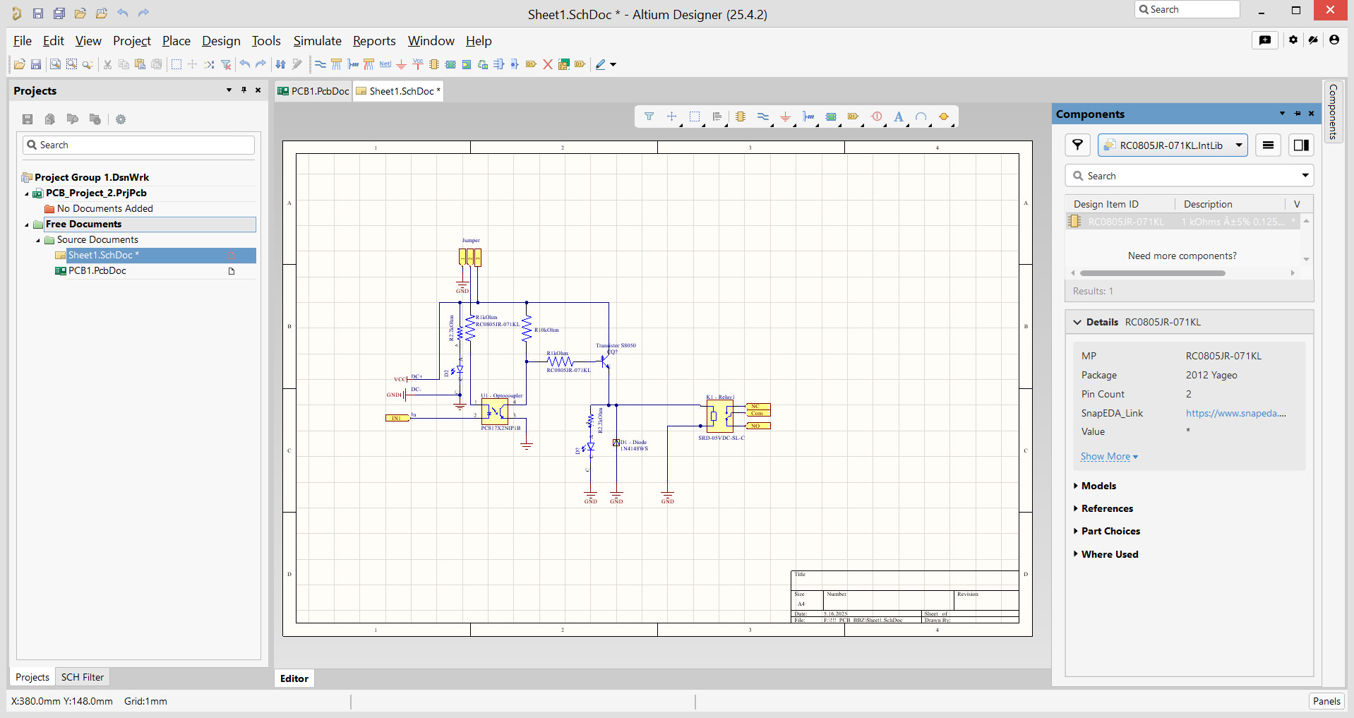
The Schematic Editor in Altium Designer 2025 is not just a schematic editor, but a powerful tool for turning engineering ideas into accurate electrical drawings. It forms the foundation of the entire electronic design process, providing an environment where creativity meets technical precision.
Whether you're a beginner, intermediate engineer, or advanced professional, this powerful tool provides an intuitive interface and comprehensive features to help you bring your electronic designs to life.
This section describes the full range of Schematic Editor features, from basic functions to the most advanced AI-powered tools.
Schematic Editor contains more than 500 unique commands and functions.
Total number of panels: 25+
Main menus: 10
Functions: 95+
Hot keys: 30+
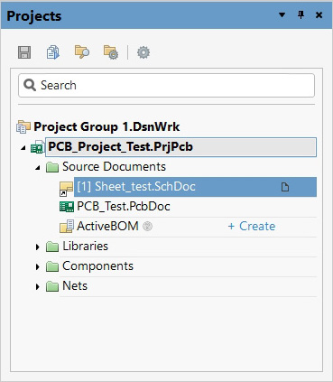
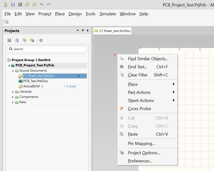
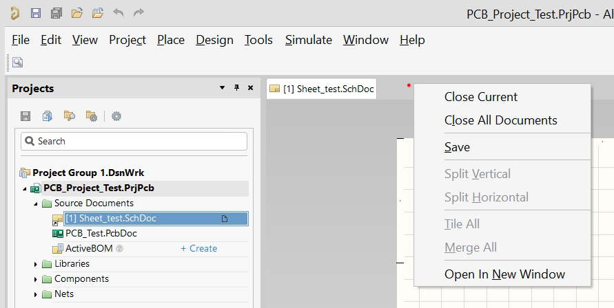
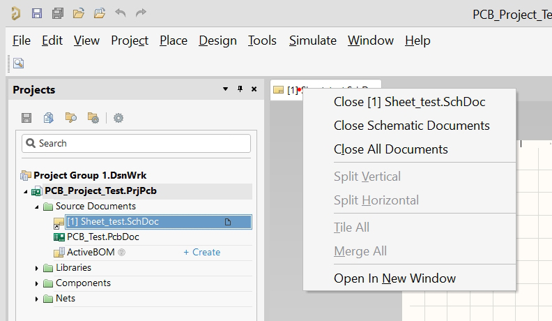
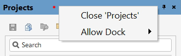
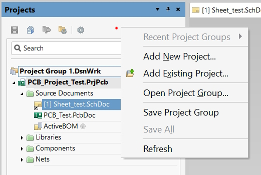
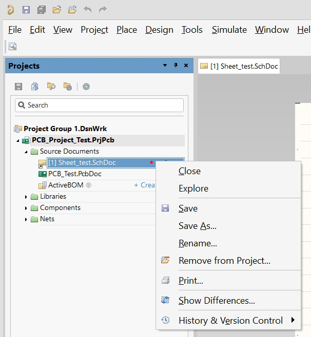
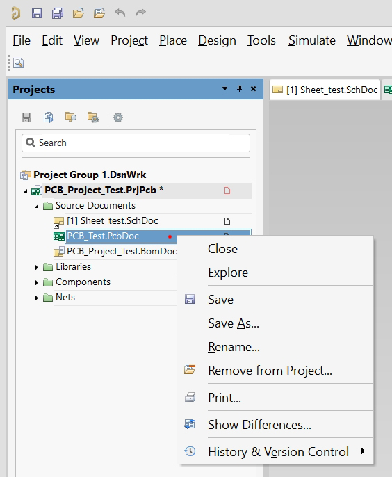
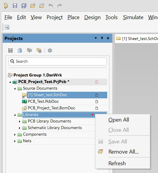
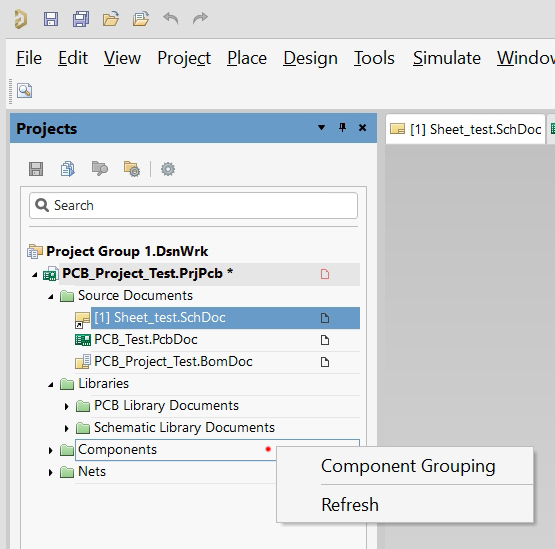
1. Projects - Project tree. Shows all files: Schematics, PCBs, libraries, documentation. The central place for project management.
2. Libraries - Component libraries (View → Panels → Libraries). Access to all symbols, seats, and 3D models. Search and place components.
3. Inspector - Object properties (View → Panels → Inspector). Edit the parameters of selected components, wires, and texts. Quickly change attributes.
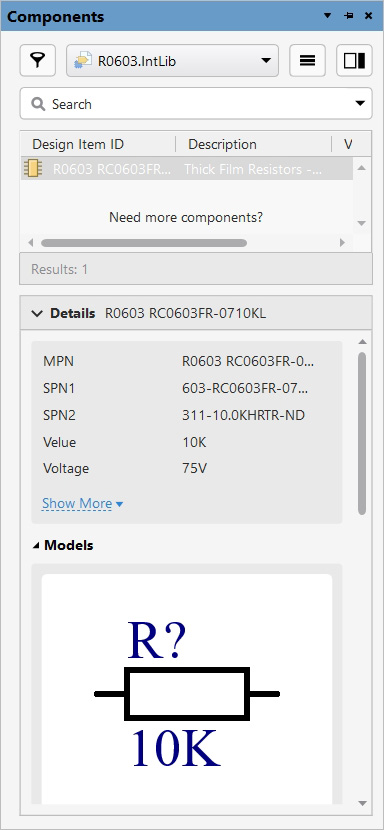
4. Components - Information about the components. Shows details, parameters, links to documentation, 3D models, and availability from suppliers.
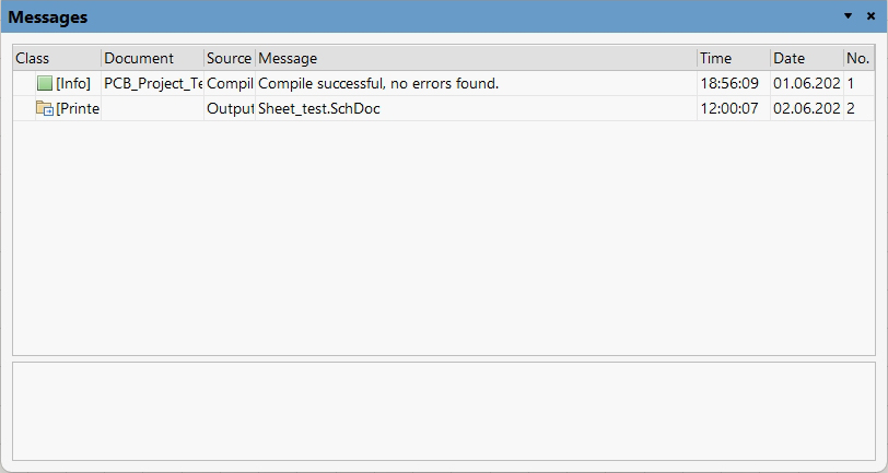
5. Messages - System messages (View → Panels → Messages). Compilation errors, warnings, information messages. Important for diagnosing problems.
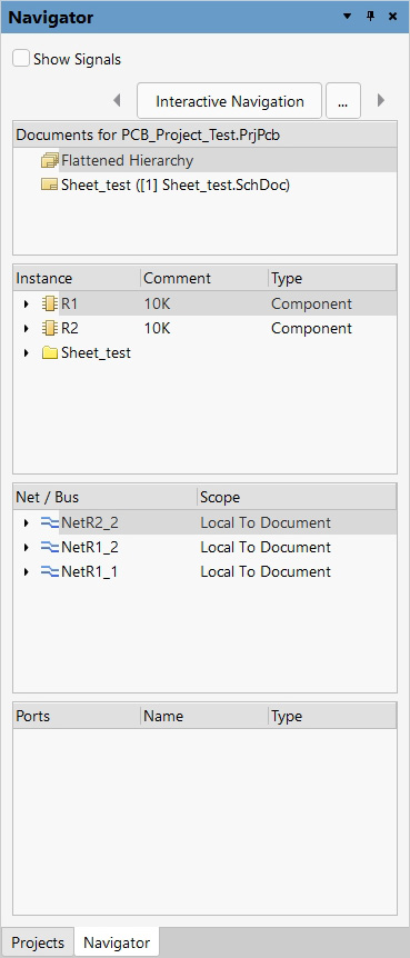
6. Navigator - Navigation through the diagram. A thumbnail of the diagram with the ability to quickly navigate to different parts. Zoom and panning.
7. Find Similar Objects - Search for similar objects. Finding all elements with similar properties (resistors of the same rating, capacitors of the same type).
8. List - List of objects. A tabular representation of all components, wires, and texts in the diagram with the ability to filter and edit.
9. Filter - Object filter. Customize the visibility of different types of objects in the diagram. Hide or highlight certain elements.
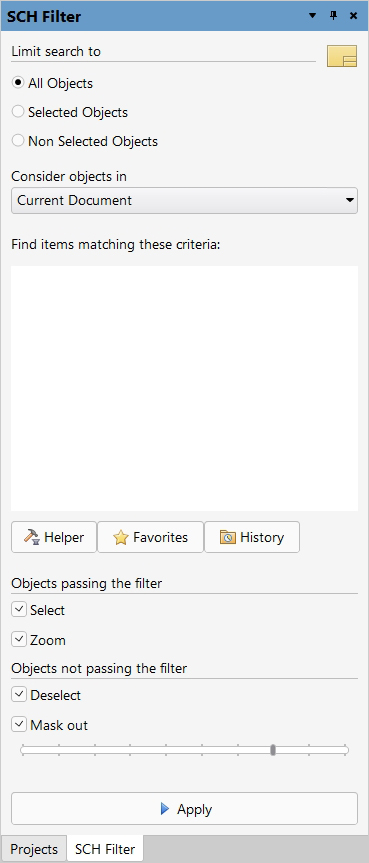
10. SCH Filter - Advanced circuit filter. Complex filtering conditions with logical operators. Search by multiple criteria - Additionally.
11. Parameter Manager - Parameter management. Centralized editing of component parameters, creation of custom parameters, bulk changes.
12. Workspace - Workspace management. Save and switch between different panel configurations and interface settings.
13. Design Rules Check - Checking the design rules. Set up and run automatic checking of the scheme for compliance with design rules.
14. Annotation - Automatic numbering. Assigns position numbers to components (R1, R2, C1, C2...). Renumbering and optimization.
15. Supplier Search - Search for suppliers. Integration with Octopart, Digi-Key, Mouser. Search for components, check prices and availability.
16. BOM - Bill of Materials. Create and edit a list of components with quantities and attributes.
17. Component Templates - Component templates. Create standardized templates to quickly add new components to your libraries.
18. Compile Errors - Compilation errors. A detailed list of all errors and warnings when compiling a project with links to problem areas.
19. Cross Reference - Cross-references. Displays all connections between component pins, including net and hierarchical connections.
20. Differences - Comparison of schemes. Identify differences between diagram versions, compare with other documents.
21. SPICE Simulation - SPICE simulation. Setting up and running simulation of analog circuits, analyzing simulation results.
22. Signal Integrity - Signal integrity. Analyze high-speed signals, impedance, delay, and crosstalk.
23. History - History of changes. Track all document modifications with the ability to revert to previous versions.
24. Output Job Manager - Manage source files. Create and customize jobs to generate Gerber, PDF, BOM, and other output documents.
25. Variant Manager - Option management. Create different configurations of the same circuit with different sets of components or parameters.
26. Live Update - Live update. Project synchronization with Altium 365, real-time change tracking, teamwork.
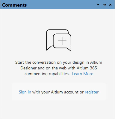
27. Comment - Comments. Add comments to the collaboration diagram, discuss changes with the team, and track reviews.
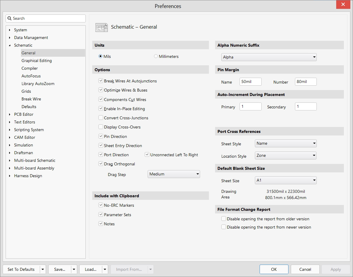
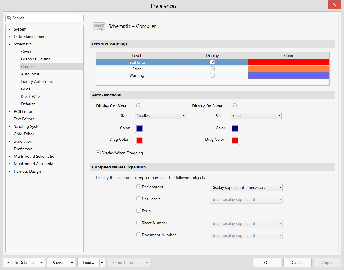
28. Document Options - Customize the document. Configure layout parameters: page size, grid, fonts, colors, templates.
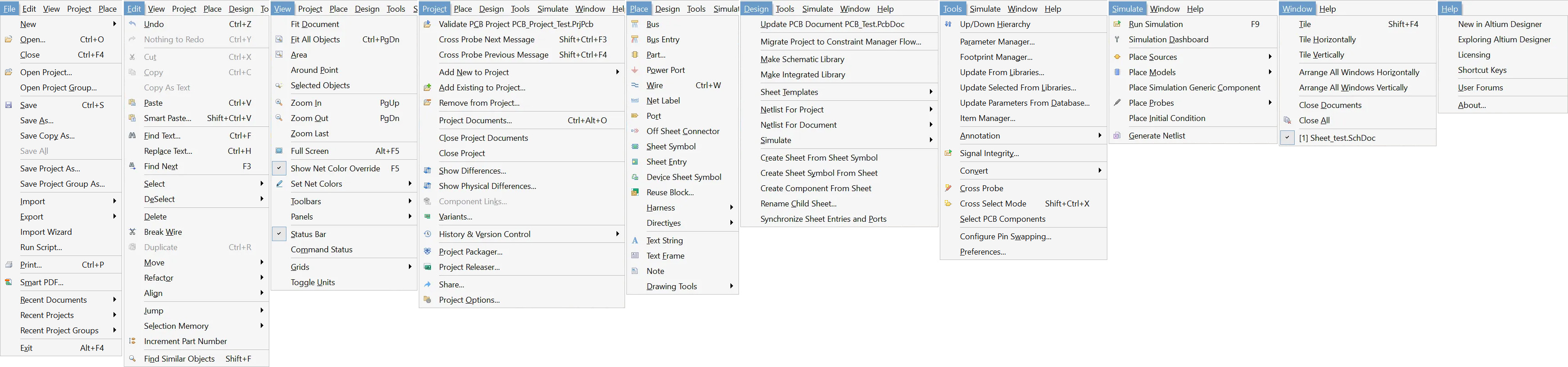
File management: create, open, save projects and documents
Key features: New, Open, Save, Import/Export, Print
Editing: basic operations for editing a diagram
Key features: Undo/Redo, Copy/Paste, Find/Replace, Select
Display: adjust visibility and zoom
Key features: Zoom, Fit, Panels, Toolbars, Grids
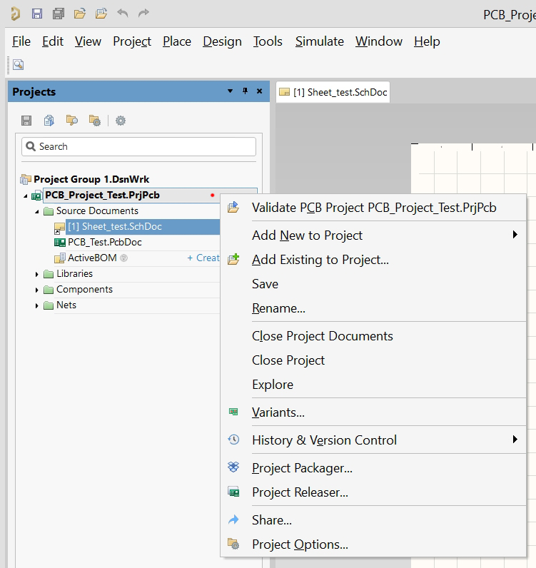
Project management: operations at the project level
Key features: Validate, Variants, Version Control, Options
Placement: add components and circuit elements
Key features: Part, Wire, Bus, Port, Text, Drawing Tools
Design: design and synchronization functions
Key features: Update PCB, Libraries, Netlist, Templates
Tools: professional management and customization tools
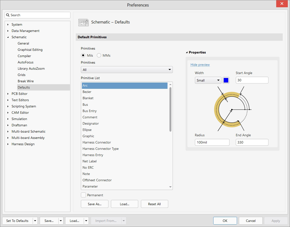
Key features: Parameter Manager, Libraries Update, Annotation, Preferences
Simulation: modeling the operation of the circuit
Key features: Run Simulation, Sources, Models, Probes
Windows: workspace management
Key features: Tile, Arrange, Close Documents
Help: training materials and support
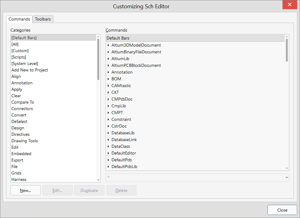
Key features: Documentation, Forums, Shortcuts, About
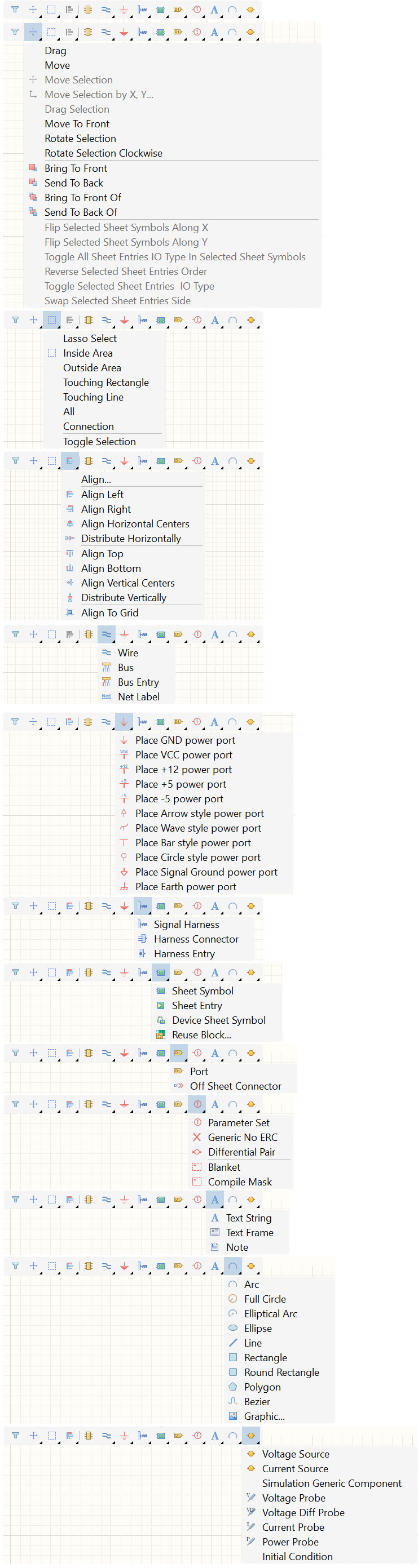
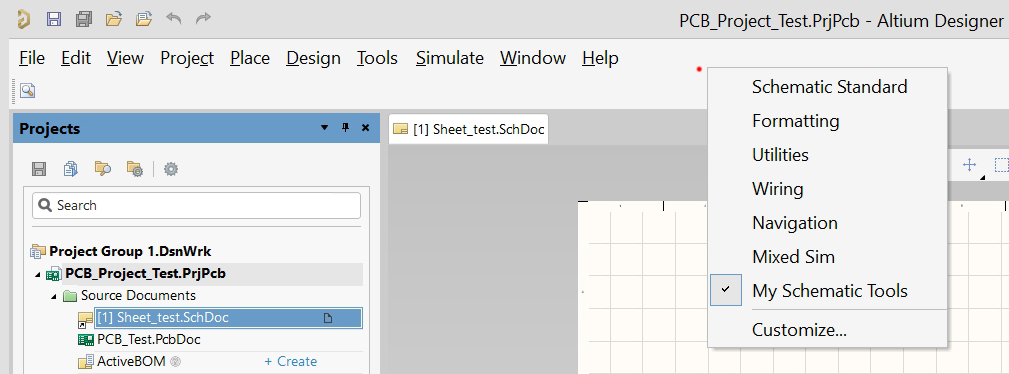
The Active Bar represents a horizontal toolbar positioned in the upper portion of the editor's workspace.
This panel contains the most demanded and frequently utilized functions specific to the current editor.
To obtain detailed information about the purpose of a particular function, it is sufficient to hover the mouse cursor over the corresponding icon - the system will automatically display a popup tooltip with a description.
Activation of any tool is accomplished by a simple left mouse button click on its icon.

| Operation | Shortcut | Description |
|---|---|---|
| Standard Keyboard Shortcuts | ||
| Place Wire | Ctrl+W | Enter wire placement mode |
| Component Properties | Double-Click | Open properties of object under cursor |
| Edit In-place | F2 | Edit selected text directly |
| Rubber Stamping | Ctrl+R | Copy selected objects and paste repeatedly |
| Select All | Ctrl+A | Select all objects on current sheet |
| Find | Ctrl+F | Search for text or components |
| Find Similar Objects | Shift+F | Find objects similar to selected one |
| Rotate Counterclockwise | Spacebar | Rotate selection 90° counterclockwise |
| Rotate Clockwise | Shift+Spacebar | Rotate selection 90° clockwise |
| Mirror X (During Placement) | X | Mirror component along X-axis |
| Mirror Y (During Placement) | Y | Mirror component along Y-axis |
| Properties Panel | F11 | Toggle Properties panel |
| Filter Panel | F12 | Toggle Filter panel |
| Measure Distance | Ctrl+M | Measure between points |
| Cross-probe to PCB | , (comma), Click | Cross-probe to PCB (Continuous Mode) |
| Board Level Annotation | Ctrl+L | Perform Board Level Annotation |
| Run Simulation | F9 | Run simulation for active design |
| Accelerator Key Sequences | ||
| Place Component | P, P | Open Components panel for placing components |
| Start Wiring | P, W | Enter wire placement mode |
| Move Object | M, M | Move selected component or object |
| Fit Document | V, D | Fit document to view |
| Fit All Objects | V, F | Fit all objects in view |
| Deselect All | X, A | Deselect all objects |
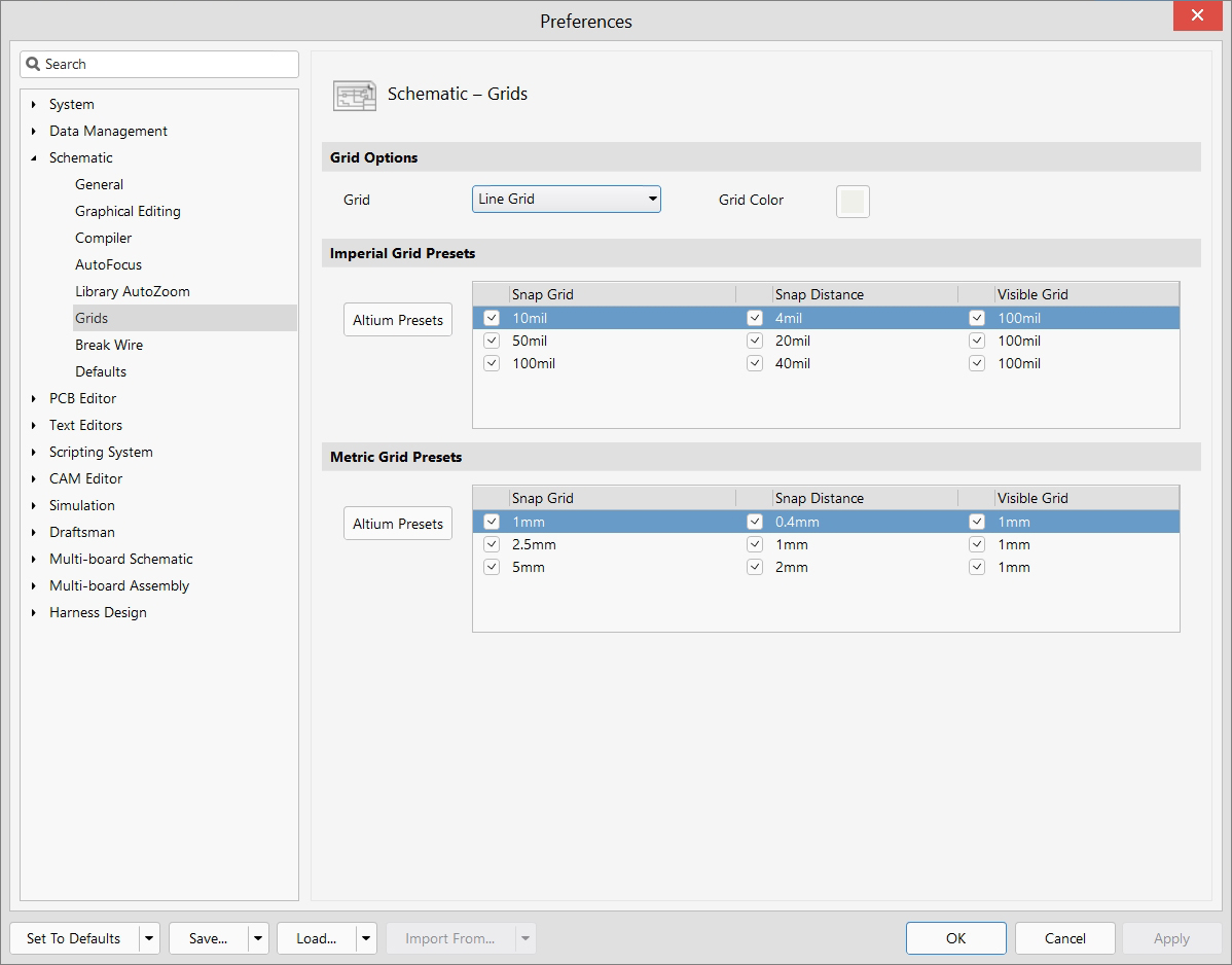
| Snap Grid Dialog | V, G, S | Open snap grid size dialog |
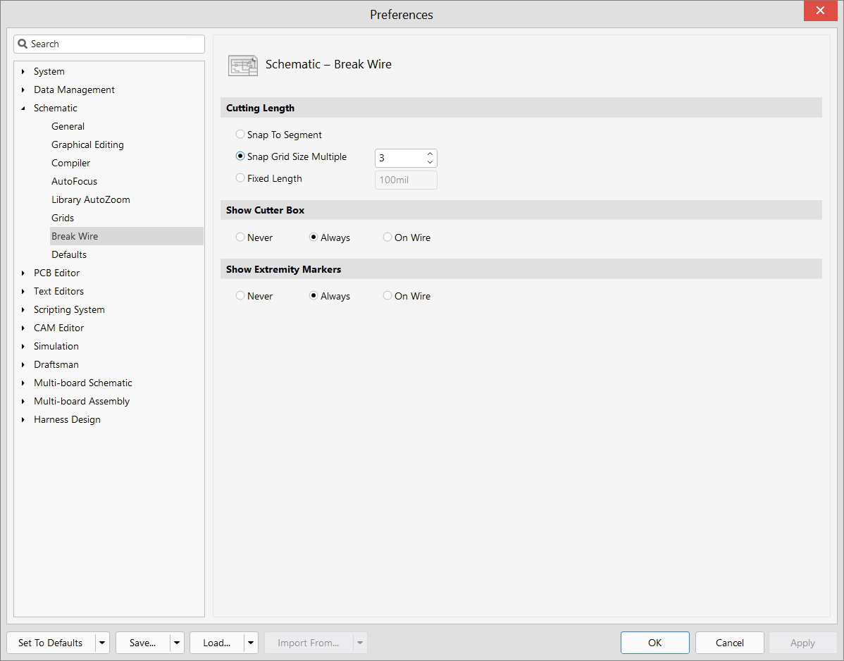
| Break Wire | E, W | Break a wire at cursor point |
| Annotate | T, A | Access the Annotate dialog |
| Reset Designators | T, A, E | Reset schematic designators |
| Reset Duplicate Designators | T, A, I | Reset duplicate schematic designators |
| Place No ERC Directive | P, V, N | Place Generic No ERC directive |
| Bill of Materials | R, I | Open Report Manager for BOM |
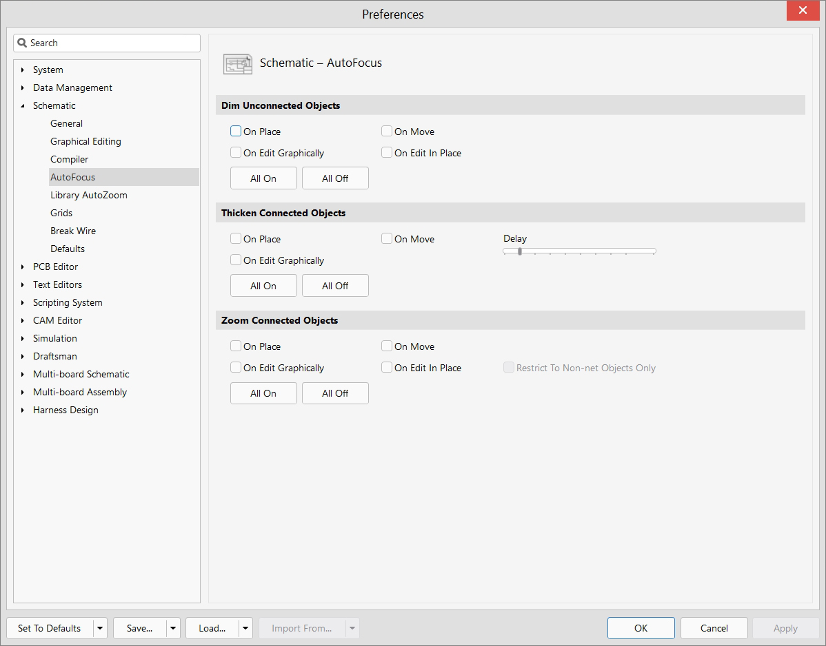
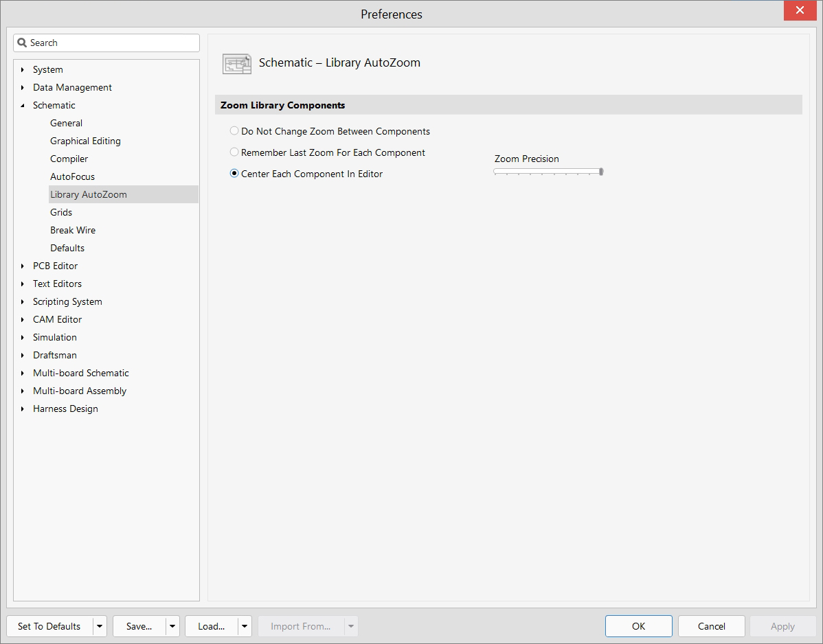
| Preferences | T, P | Open Schematic Preferences dialog |
| Term | Definition |
|---|---|
| Annotation | Process of automatic or manual assignment of unique identifiers to components on a schematic |
| Bus | Group of signals combined by functional characteristics, represented as a single line |
| Component | Electronic element of a circuit consisting of a symbol (graphical representation) and model (electrical characteristics) |
| Cross-Probe | Mutual highlighting of objects in both schematic and PCB, allowing for easy identification of corresponding elements |
| Device Sheet | A typical schematic block used as a standardized module for reuse across multiple designs |
| Directive | Special instruction that affects the behavior of the circuit during simulation or project compilation |
| Dynamic Compilation | Automatic real-time schematic updating that maintains project integrity during edits |
| ECO (Engineering Change Order) | Process of synchronizing changes between schematic and PCB |
| ERC (Electrical Rule Check) | Verification of electrical rules in the schematic to identify potential errors and issues |
| Harness | Grouped set of wires connecting components between different parts of the schematic |
| Hierarchical Design | Project structure with nested sheets and subschemas allowing for organization of complex designs |
| Junction | Connection point of three or more wires on a schematic |
| Multi-channel Design | Method of creating a schematic with repeating identical channels, reducing development time and simplifying maintenance |
| Net | Electrical connection between components that defines signal routing |
| PLM (Product Lifecycle Management) | System for managing the complete lifecycle of a product from initial concept through design, manufacturing, and obsolescence |
| Port | Element representing electrical connection between different sheets in a hierarchical project |
| Schematic | Graphical representation of an electronic circuit showing components and their connections using standardized symbols |
| Sheet | Separate schematic sheet in a project |
| Sheet Symbol | Graphical representation of a subschema at a higher hierarchy level that references a child sheet |
| SPICE | Simulation Program with Integrated Circuit Emphasis - software for electronic circuit simulation and analysis |
| Variant | Alternative version of the project with different components or parameters while maintaining the same base design |
| Wire | Electrical connection between component pins on a schematic, representing a physical conductor |