Design Editors
Powerful design creation tools forming the foundation of Altium Designer, enabling engineers to transform concepts into production-ready electronics.
Powerful design creation tools forming the foundation of Altium Designer, enabling engineers to transform concepts into production-ready electronics.
The Design Editors in Altium Designer 2025 form a comprehensive suite of tools that enable engineers to seamlessly progress from concept to production-ready electronics. Each editor is purpose-built for specific aspects of the design process while maintaining tight integration with the entire platform.
Define your project structure and create component building blocks. Establish a solid project foundation by organizing file structures and building high-quality component libraries. This stage streamlines your entire development process with version control, supplier database integration, and detailed component models that ensure mechanical compatibility.
1. Design Project Manager ~30-40 unique commands
Related panels: Projects panel, Storage Manager panel, Version Control panel, Project Options panel, Variants panel
2. Component Library Manager ~50-60 unique commands
Related panels: Library panel, Component List panel, Supplier Search panel, Parameters panel, Models panel
3. Symbol Editor ~30-40 unique commands
Related panels: Pin Manager panel, Symbol Properties panel, Component Editor panel, Symbol Library panel, Drawing Tools panel
4. Footprint Editor ~40-50 unique commands
Related panels: PCB Library panel, Properties panel, Pad Properties panel, Primitive Properties panel, Footprint Manager panel
5. 3D Body Editor ~20-30 unique commands
Related panels: 3D Body Items panel, 3D Body Properties panel, Generic Models panel, 3D Visualization panel, STEP Model panel

Transform engineering concepts into functional schematics and validate designs before physical implementation. This phase encompasses comprehensive design verification through simulation, signal integrity analysis, constraint management, and multi-layer stackup configuration.
6. Schematic Editor ~100-120 unique commands
Related panels: SCH Library panel, SCH Inspector panel, Navigator panel, Nets panel, Electrical Rules panel
7. Simulation Editor ~30-40 unique commands
Related panels: Mixed Sim panel, Waveform Analysis panel, SPICE Model Manager panel, Signal Integrity panel, Simulation Dashboard panel
8. FPGA Design Integration ~40-50 unique commands
Related panels: FPGA Configuration panel, Pin Mapping panel, HDL Project panel, Constraints panel, Signals panel
9. Constraint Manager ~25-35 unique commands
Related panels: Constraint Manager panel, Rule Priority panel, Design Rules panel, Differential Pairs panel, xSignals panel
10. Layer Stack Manager ~20-30 unique commands
Related panels: Layer Stack panel, Layer Properties panel, Impedance Profiles panel, Dielectric Material panel, Signal Layer panel
11. PDN Analyzer ~25-35 unique commands
Related panels: PDN Summary panel, Power Nets panel, DC Drop Analysis panel, Thermal Analysis panel, Net Connectivity panel
12. PCB Editor ~150-180 unique commands
Related panels: PCB panel, Properties panel, PCB Inspector panel, Design Rule Checker panel, Board Planning Mode panel, 3D Layout Mode panel

Move beyond single boards to create complex electronic systems that integrate multiple devices into cohesive products. This design level enables sophisticated multi-board assemblies with cable harnesses and 3D-formed interconnects, ensuring precise spatial coordination and electrical compatibility.
13. Multi-board Editor ~40-50 unique commands
Related panels: Multi-board Assembly panel, Connection Manager panel, Placement panel, 3D Mode panel, System Browser panel
14. 3D-MID Editor ~25-35 unique commands
Related panels: 3D MID Surface panel, 3D Routing panel, Component Placement panel, Manufacturing Settings panel, MID Properties panel
15. Harness Designer ~35-45 unique commands
Related panels: Harness Definition panel, Cable Manager panel, Wire Properties panel, Connector panel, Harness Documentation panel

Prepare your designs for flawless production with comprehensive technical documentation and manufacturing outputs. This final stage optimizes bills of materials, automates assembly drawings, and generates production-ready files that accurately translate engineering intent into finished products.
16. ActiveBOM ~30-40 unique commands
Related panels: BOM panel, Supplier Search panel, Part Choices panel, Cost Analysis panel, Component Status panel
17. Output Job Editor ~25-35 unique commands
Related panels: Output Container panel, Output Generator panel, Output Settings panel, Templates panel, Batch Process panel
18. CAM Editor ~35-45 unique commands
Related panels: CAM View panel, Layer panel, Aperture panel, NC Drill panel, Comparison panel
19. Draftsman ~40-50 unique commands
Related panels: Drawing panel, Assembly panel, Detail View panel, Drawing Views panel, Fabrication panel
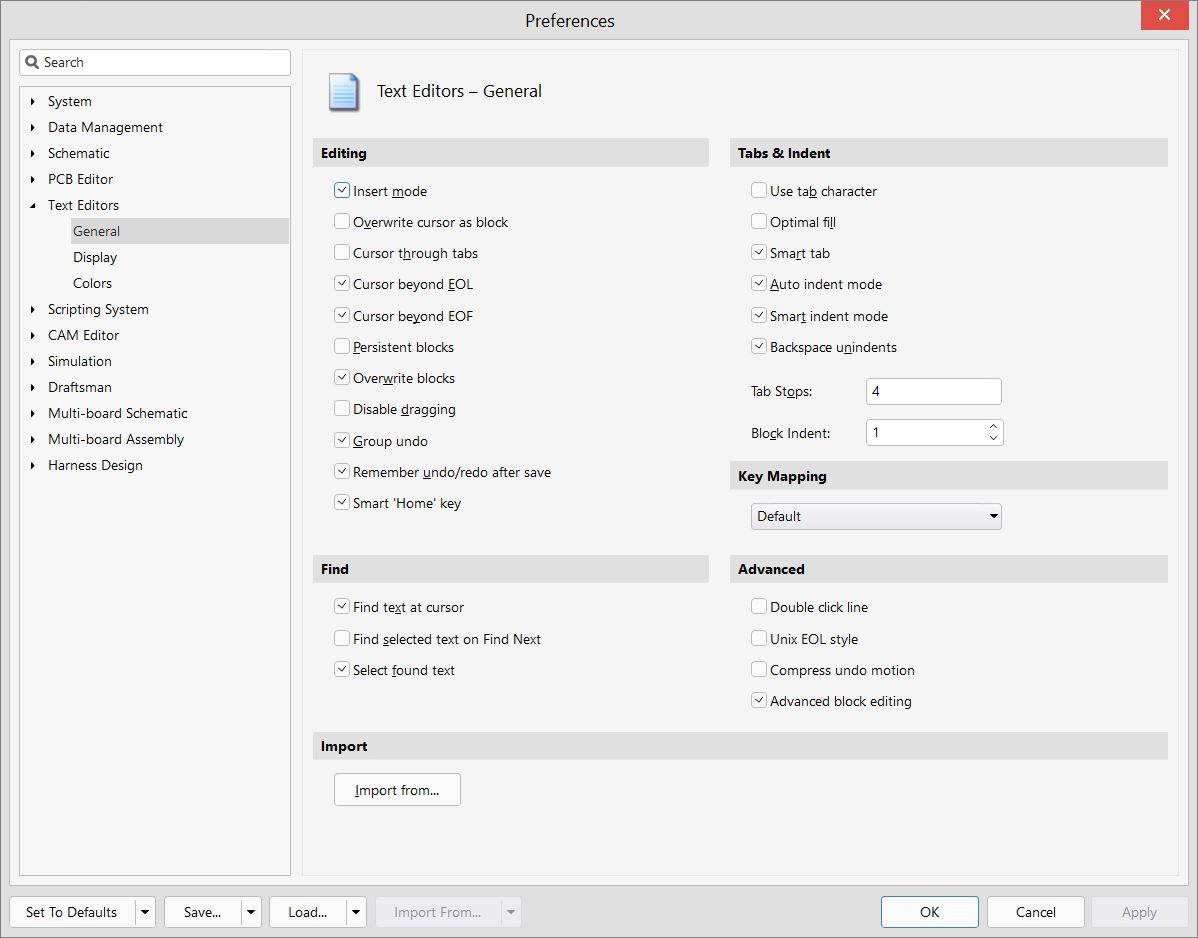
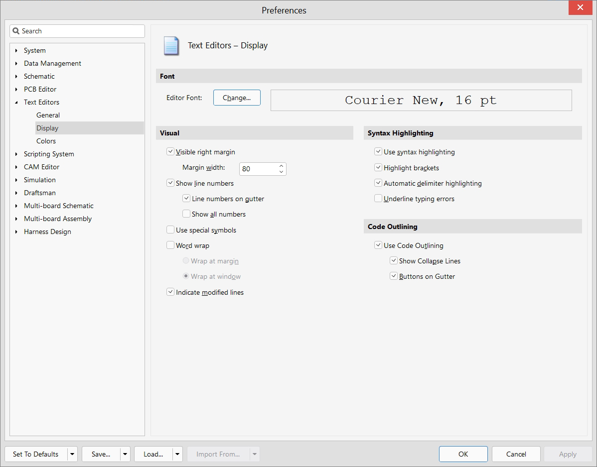
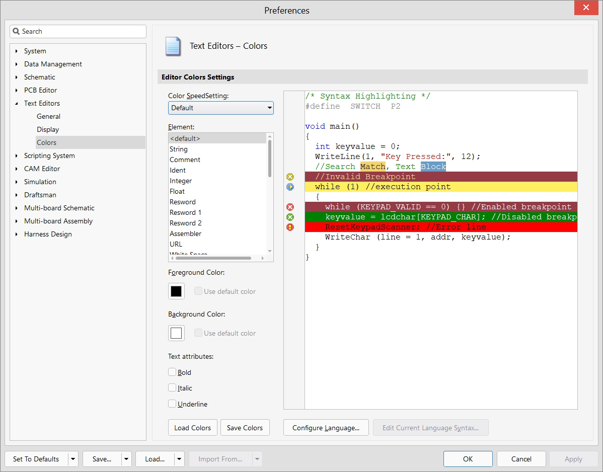
20. Scripting Editor ~30-40 unique commands
Related panels: Script Editor panel, Execution panel, Code Explorer panel, Debug panel, Script Library panel
Total for all editors: approximately 820-1000 unique commands.
This comprehensive organization reflects the typical electronic design workflow from concept to manufacturing. Each editor is purpose-built for specific aspects of the design process while maintaining tight integration with the entire platform. Understanding these tools in their workflow context helps engineers navigate the complete design process efficiently, from initial project setup through component creation, schematic design, PCB layout, to final manufacturing documentation.